| Engineering Acoustics - EEN502 Michael Battaglia Project 1 |
|
|
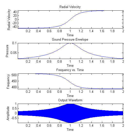
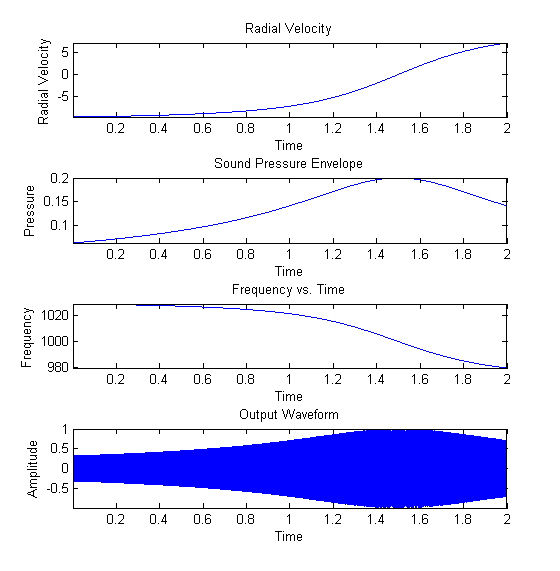
Part 2 - ObjectiveSet up the experiment so that you can specify the minimum distance of the observer from the source trajectory, and repeat (1). Produce a set of results as in part (1) for the listener at some distance away from the source trajectory. Solution: Matlab Code The implemention of this part of the project was similar to that of part 1. The trajectory of the source here is treated as a horizontal line on which the observer is placed a certain distance away from. The source is initially placed at the far left of the line, and moves towards the far right. The following plots reflect a trajectory length of 100 m, a velocity of 50 m/s, and an observer located at 50 m from the left of the start trajectory and 10 m away from the closest point on the line. F0 is 440 Hz. One problem I ran into here is that initially, the output waveform did not accurately represent the frequency shift predicted by the doppler equation. This is because the initial formula I was using - p*sin(2pi*f*t), where p is the pressure envelope and f is the frequency vector as a function of time - is not quite the exact formula for frequency modulation of a signal. In the digital domain, the shift between the frequencies of the output signal simply occurs by simply switching from one sine wave at a certain frequency to another. The two waves both start at phase 0 when t = 0, and are then set to free run. This means that as the sine waves are switched, discontinuities in the signal are introduced as a result of phase distortion. When the frequency changes rapidly as the result of a Doppler-esque frequency sweep, these continuous phase distortions present themselves as a sort of aliasing in which a tone not expected is heard. The way around this is to implement what is called Continuous-Phase Frequency-Shift Keying (CPFSK), which would eliminate such distortion. To implement CPFSK, the following equation is used:  Where Ac represents the amplitude of the CPFSK signal, fc is the base carrier frequency, and Df is a parameter that controls the frequency deviation of the modulated signal. (http://en.wikipedia.org/wiki/Continuous-phase_frequency-shift_keying#Continuous-phase_frequency-shift_keying) The m(alpha) term here is closely related to the radial velocity, and the integral of the radial velocity in this case is the radius itself. As an approximation, the formula p*sin(2pi*f0*t - 2pi*r), where r is the radius vector as a function of time, created a nearly correct output - but the doppler frequency shift was scaled down a bit from what it should be. Through trial and error, the phase term 3pi*r rather than 2pi*r was closer to the correct output - but not exact. The exact math to calculate the integral in this case was a bit overwhelming, so a much better approximation was used: by phase-locking all of the frequencies at the point where the source is closest to the observer, rather than where the source originates its motion, the distortion will be minimized for the output signal and for the purposes of this project completely eliminated. This approach would fail if the source ever came back around for a second pass, but for the purposes of this experiment, the approximation serves nicely. Here is another plot for comparison. The trajectory here is 20 m, the velocity 10 m/s, and the observer is located on the right at 15 m from the source origin and back 5 meters. The source is emitting a 1000 Hz tone. |

